- Assume that an ISA level instrcution on the 8088 is interpreted to 3 instructions at the hardware level, on average.
- Assume that an ISA level instrcution on the Core i7 is interpreted to 5 instructions at the hardware level, on average.
The Core i7 can simulate the 8088 instruction set. Assume that each ISA level instruction from the 8088 can be interpreted to 2 ISA level instructions on the Core i7.
- How many milliseconds would it take to run 1,000,000 8088-ISA level instructions on this 8088?
- How many milliseconds would it take to run 1,000,000 Core i7 instructions on this Core i7?
- How many milliseconds would it take to run 1,000,000 8088-ISA level instructions on this Core i7?
- The 8088 was a dedicated machine for its ISA. The Core i7 can interpret the 8088 ISA. Is a hardware implementation always faster than a software implementation?
- First Intel computer with a single, five-stage pipeline
- First Intel computer with a dual, five-stage pipeline
- First Intel computer with a superscalar pipeline
- First product line developed as a family.
- Computer that marked the start of modern computer history.
- First vector computer.
- First commercial RISC machine
- First computer with a bus for I/O
- First dual-core chip.
Interp function from class. The main program has been given already, write all the missing routines.
I have modified the code a little from the example from class. The find_data returns the location of the data, not the data. This allows more flexibility.
    int PC;
    int ACC;
    int instr;
    int instr_type;
    int data_loc;
    int data;
    boolean run_bit = true;

    public void Interp(int starting_address) {
        PC = starting_address;
        while (run_bit) {
            instr = memory[PC];
            PC = (int) (PC + 1);
            instr_type = get_instr_type(instr);
            data_loc = find_data(instr, instr_type);
            execute(instr_type, data_loc);
        }
    }
If you already have an idea of how to implement this, then use your idea. If you are stuck, here are a few suggestions for a simple architecture.
- Have a limited number of instructions, like: ADD, SUB, LOAD, STORE, LOAD_CONSTANT, HALT.
- Use bit patterns for each instruction, not symbols like above.
- Decide on an 8-bit instruction.
- With six instructions, you will need three bits to represent all the above operations. You could add two more instructions and not need an additional bit for the operation part of the instruction.
- Use the remaining number of bits to address memory. So, memory will 32 bytes, since five bits are left in the instruction to address memory.
-
Most instructions use the accumulator. The only ones that don't are HALT and LOAD_CONSTANT.
- The add instruction adds a value from a memory location to the accumulator.
- The sub instruction subtracts a value from a memory location from the accumulator.
- The load instruction reads a memory location and places it in the accumulator.
- The store instruction saves the accumulator to a memory location.
- The load_constant instruction treats the address portion of the instruction as a constant to be loaded into the accumulator. It does not access memory.
- The halt instruction sets the run bit to false and should be the last instruction in a program.
A program can be as simple as:
- load a constant into the accumulator
- store the accumulator to a memory location
- load another constant into the accumulator
- add the stored memory location to the accumulator
- store the accumulator to another memory location
- halt
After the program is interpretted, display the contents of the 32 bytes of memory, to see if your program worked.
- Store the data using Big Endian
- Store the data using Little Endian
- How many cycles are needed to add seven to each element in the array on a multiprocessor with four cores?
- The partial-sum array for an array is another array that contains the sum of the elements in the array, up to each index. The first element is the first element of the original array, the second element is the sum of the first two elements in the original array, etc. How many cycles are needed to create the partial-sum array on a multiprocessor with four cores?
      A OR B
      (A OR B)C OR (A OR B)(NOT C)
- Prove whether or not these equations are equivalent by using truth tables. Do not simplify the expressions.
- Prove whether or not these equations are equivalent by using Boolean logic to simplify one formula to the other.
- Create a truth table for a circuit that is one when the parity of its three inputs is even.
- Write a Boolean formula as a sum of products that represents the truth table for the circuit.
- Draw a circuit diagram for this function using only 2-input NOR gates.
- Draw a circuit diagram for this function using the MSI multiplexer chip in the Multiplexers section of the book. Do not draw the inside of the multiplexer.
- Draw the truth table for a 2-bit encoder. There will be four input variables and two output variables. Only one of the input variables can be 1 at a given time, so there are only 4 possible combinations for valid input variables.
- Draw the circuit for the 2-bit encoder.
-
Draw the circuit for a 3-bit encoder. There will be 8 input lines and
3 output lines.
- Draw the truth table for a half-subtractor.
- Draw the circuit for a half-subtractor.
- Draw the truth table for a full subtractor.
- Draw the circuit for a full subtractor.
- A OR B
- The constant 1
- The constant -1
- B - A
- In terms of the input values for clock and data,
- when will Latch A be in a nondeterministic state (both input lines are 1)?
- when will Latch B be in a nondeterministic state?
- when does Latch C change its state?
- if Output 1 is 0, when does it change to 1?
- if Output 2 is 0, when does it change to 1?
- In ten words or less, what is this circuit?
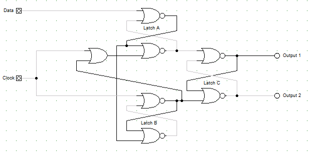
I have created a running example of this circuit using digital works. Download digital works and my example to run it