CDA-4101 Lecture 16 Notes


Mic-1 ALU


Mic-1 ALU Operations

Here are some of the useful possible combinations of ALU control signals:

F0 F1 ENA ENB INVA INC Function
0 1 1 0 0 0 A
0 1 0 1 0 0 B
0 1 1 0 1 0 A'
1 0 0* 1 0 0 B'
1 1 1 1 0 0 A + B
1 1 1 1 0 1 A + B + 1
1 1 1 0 0 1 A + 1
1 1 0 1 0 1 B + 1
1 1 1 1 1 1 B - A
1 1 0 1 1 0* B - 1
1 1 1 0 1 1 -A
0 0 1 1 0 0 A AND B
0 1 1 1 0 0 A OR B
0 1 0 0 0 0 O
1* 1 0 0 0 1 1
0 1 0 0 1 0 -1

  • Minus means two's complement ("-")

  • Mic-1 ALU, Shifter and Timing

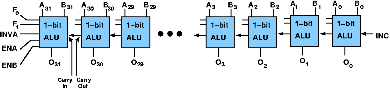
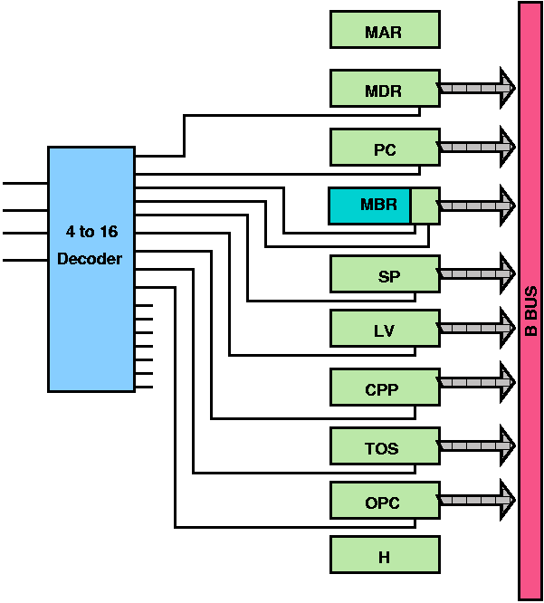
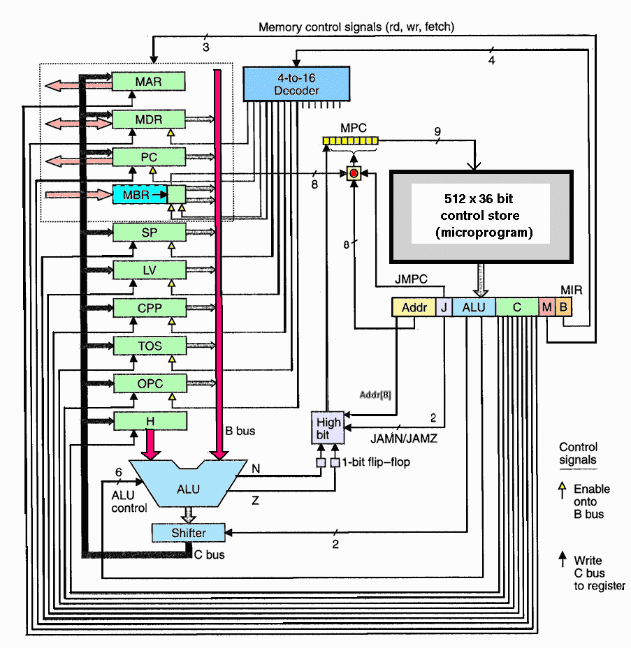
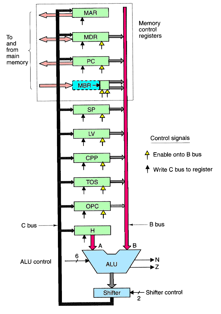
    • Holding Register (H)is the left ALU input. To load, you must pass something on B bus through ALU and shifter without modification and then store it in H.
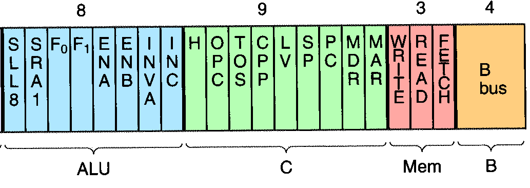
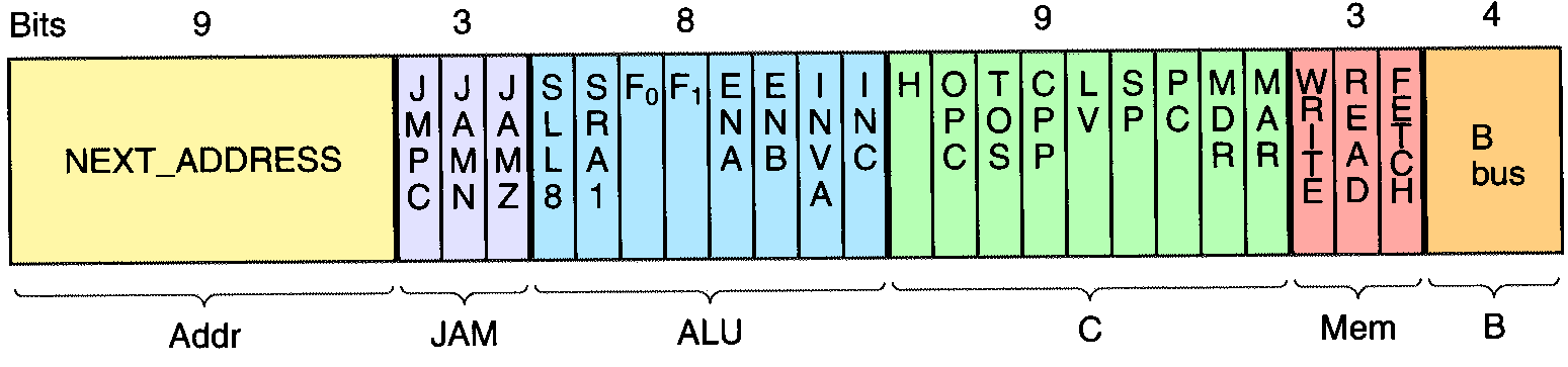
    • Shifter has two control inputs:
      • SLL8 - Shift Left Logical, will shift ALU contents left by one byte, adding zeroes to low order 8 bits.
      • SRA1 - Shift Right Arithmetic, shift the ALU contents one bit to the right, but leaving the most significant byte (the sign bit) unchanged

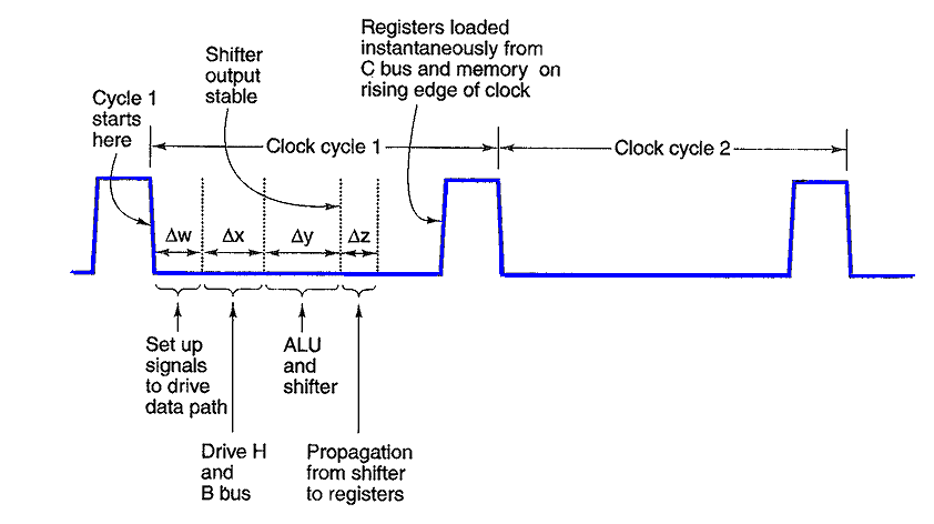
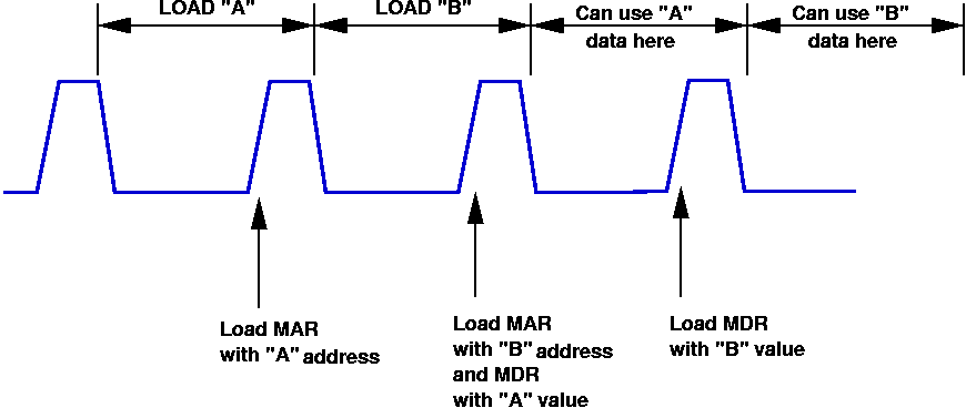
    • You can read and write the same register on a single cycle.
      1. The contents are put on B bus early in cycle
      2. time is allowed for ALU and Shifter to operate
      3. then toward the end of the cycle, the edge-triggered registers will load

    Data Path Timing


    Mic-1 Memory Operations

    • Two ports into memory
      • 32 bit port
      • 8 bit port
    • 32-bit port: (Data Cache interface)
      • MAR - Memory Address register specifies the memory address to use for a memory operation (LOAD or STORE)
      • MDR - Memory Data Register serves as destination or source for LOAD and STORE operations
      • note that you cannot put the MAR contents on the B bus
    • 8-bit port: (Instruction Cache interface)
      • PC - Program Counter serves as the address pointer into memory
      • MBR - Memory Buffer Register serves as destination for memory contents (i.e., opcodes and their other fields)
      • MBR only loads single byte because IJVM op-codes are only a single byte, not 32 bits.
      • can only read from memory into the MBR register
      • cannot write from C bus to MBR register

    MAR and PC Addresses


    Gating MBR onto the B Bus

    • Two ways to put the one byte MBR onto the B bus:
      • unsigned - MBR into low order 8 bits and zeroes in upper 24 bits
      • signed - MBR into low order 8 bits and duplicate the sign bit in all upper 24 bits. i.e., treat as a signed integer and just convert it from an 8 bit represetnation to a 32 bit representation, e.g.,
             0000 0101    => 0000 0000   0000 0000   00000 0000   0000 0101
             1100 0101    => 1111 1111   1111 1111   11111 1111   1100 0101
            
        (called sign extension)
    • the two control lines into the MBR register select one of the two ways to do this.

    Mic-1 Microinstructions

    • need 29 control signals to operate the full data path (and memory)
      • 9 signals to control writing from C bus into regsiters
      • 9 signals to control putting registers onto B bus
      • 8 signals to control the ALU and Shifter
      • 2 signals to signal memory read/write via MAR and MDR (not shown)
      • 1 signal to indicate memory fetch via PC and MBR ( not shown)
    • values on these 29 control lines will dictate the exact operation for one cycle of the data path

    Mic-1 Memory Timing


    Back-toBack Memory Reads


    Reduction of Control Signals

    • we may want to have the ALU output latched into more than one register
    • we cannot put two registers on the B bus at the same time
    • There are 9 control signal defining which register gets on the B bus
    • We can encode the 9 B bus signals as a binary number and only need 4 control signals
    • we use a decoder between these 4 signals and the 9 real control signals
    • we can now control the data path with just 24 control signals (29-9+4)

      Binary
      Value
      Register
      Enabled
      0 MDR
      1 PC
      2 MBR
      3 MBRU
      4 SP
      5 LV
      6 CPP
      7 TOS
      8 OPC
      9 - 15 none

    MIC-1 Microinstruction Format


    Complete Mic-1 Microarchitecture


    Layers of Complexity: Roadmap