CDA-4101 Lecture 17 Notes


Complete Mic-1 Microarchitecture


Mic-1: Microinstruction Control


Mic-1 Control Store


Instruction Sequencing


MPC and MIR Registers

  • just like we need a program counter (PC) and instruction register (MBR) to be able to execute an ISA program, we need similar registers to be able to execute the microprogram
  • The MPC is the MicroProgram Counter: this is really not a counter, but simply a register holding the 9 bit address of the next microinstruction
  • The MIR is the MicroInstruction Register: holds the currently executing microinstruction
  • The MPC will contain the 9 bit address field of the microinstruction, with a possible altering from the JAM field bits if branching

Mic-1 Control Section

Microarchitecture Operation

  • clock cycle starts with falling edge of clock
  • MIR loaded from control store according to address contained in MPC (MIR register consists of trailing edge triggered flip-flops)
  • Δw is the time it takes for the MIR to load and have stable outputs
  • Δx is the time it takes for the control signals to propogate, data from the registers to be stable on the A and B buses, and the ALU/Shifter control signals to have ALU operation configuration stable
  • Δy is the time it take for the ALU input values to propogate through the ALU and shifter and for the N and Z ALU outputs to be stable
  • Δz is the time it takes for the ALU/Shifter outputs to propagate to the C bus (register input pins)
  • At the rising edge of the clock:
    1. the contents of the C bus are loaded into the appropriate registers (as determined by the MIR fields);
    2. the ALU outputs N and Z are latched into a pair of one-bit flip-flops
    3. if needed, memory data is latched into MDR or MBR registers
  • a short time after the rising edge, while the clock is still high, MPC gets its value
  • we are then back where we started and this continues as long as there is power to the circuits

Mic-1 Control Section

Calculating the Next Microinstruction Address


Altering MPC's High Order bit

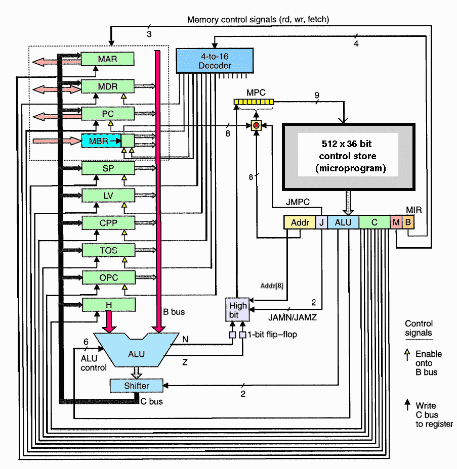
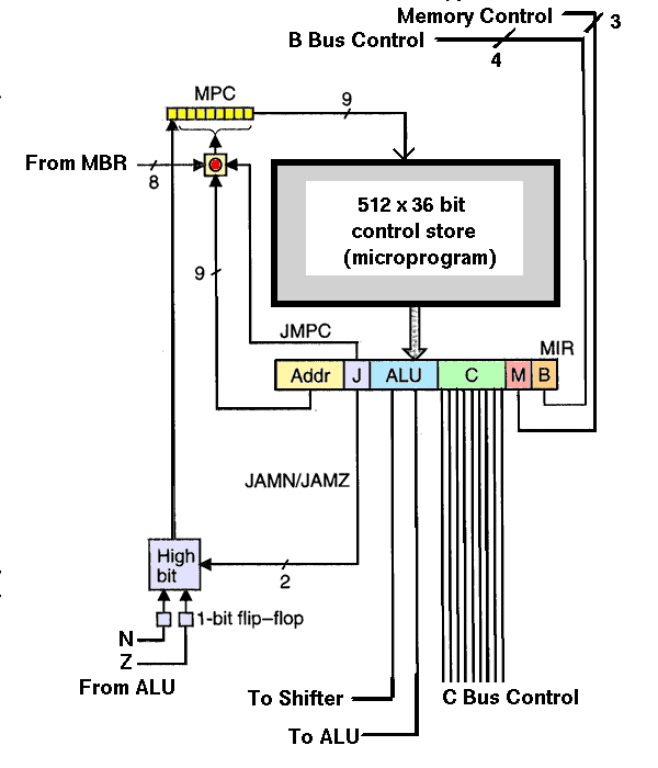
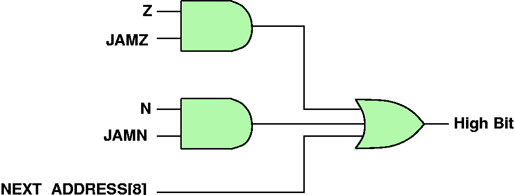
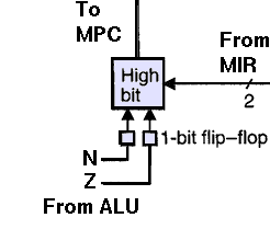
  • "High Bit" box in diagram contains the logic to compute the MPC's high-order bit
  • this allows the next microinstruction's address to be determined (altered) by the results of an ALU computation
  • in particular, the ALU outputs N and Z can be used to alter the next microinstruction address
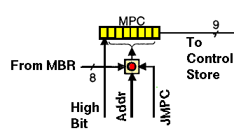
  • need 1-bit flip-flops for N and Z because after rising edge of clock, B Bus is no longer being driven, so we must assume ALU output is not valid (we use N and Z to determine the value of MPC after the rising edge of the clock.
  • Let NEXT_ADDRESS[8] be the high-order bit of the address field for a microinstruction, then the truth table for the outputs of the "High Bit" box are ("+" means logical OR):
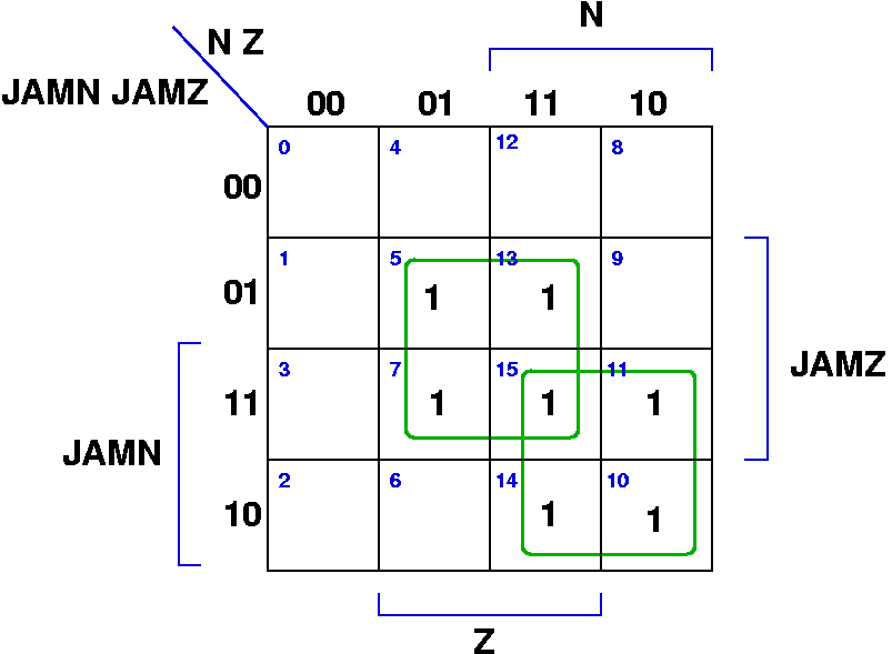
    JAMN JAMZ High Bit
    Output
    0 0 NEXT_ADDRESS[8]
    0 1 NEXT_ADDRESS[8] + Z
    1 0 NEXT_ADDRESS[8] + N
    1 1 NEXT_ADDRESS[8] + Z + N

  • the idea is that by changing the high-order bit, you can change the address and thus the next instruction fetched from the control store.
  • The high order bit function should be (see next slide for details):

    HighBit = (JAMZ · Z) + (JAMN · N) + NEXT_ADDRESS[8]

  • since high-order value of MPC comes either directly from a microinstruction, or is OR'ed with something that is '1', if the microinstruction already had the high-order address set to '1', there is really no need to have any concern about the values of the N and Z ALU outputs (since it will not change the value of MPC.)
  • The effective value of the high order bit (assuming NEXT_ADDRESS[8] = 0) is:

    HighBit = (JAMZ · Z) + (JAMN · N)

High Bit Computation: Gorey Details

N Z JAMN JAMZ High Bit
0 0 0 0 0
0 0 0 1 0
0 0 1 0 0
0 0 1 1 0
0 1 0 0 0
0 1 0 1 1
0 1 1 0 0
0 1 1 1 1
1 0 0 0 0
1 0 0 1 0
1 0 1 0 1
1 0 1 1 1
1 1 0 0 0
1 1 0 1 1
1 1 1 0 1
1 1 1 1 1
  • This gives us the equation:

    HighBit = (JAMZ · Z) + (JAMN · N)


Next Address Example


JMPC Field

  • the third JAM bit is JMPC and when it is set, the low order 8 bits of the microinstruction's address field is logically OR'ed with the contents of the MBR
  • typically we only want the contents of MBR, so we set the low-order bits of the microinstruction's address field to 0x00.
  • we can set the high-order (i.e., 9th bit) of the address field to either 0 or 1 (we discuss later what all of this means)

JMPC Computation Details

JMPC MBR[i] NEXT_ADDRESS[i] MPC[i]
0 0 0 0
0 0 1 1
0 1 0 0
0 1 1 1
1 0 0 0
1 0 1 1
1 1 0 1
1 1 1 1
  • This gives us the equation:

    MPC[i] = NEXT_ADDRESS[i] + (JMPC · MBR[i])


JMPC Computation


What's JMPC For?