Lab 1: Simple Network Emulation with GNS3
Overview
The goal of this project is to install and configure GNS3 software and emulate/configure a simple network.
Tasks
1. Install GNS3 Software
Go to GNS3 Webpage and download GNS3 application for your platform. It is available for Windows, Mac, and Linux.
2. Download router images from Canvas
While the software itself is free and it can emulate various types of hardware, the licensing of actual Cisco software is a complex issue.
For this and future labs we will need Cisco 3660 and Cisco 7200 platforms and you can download c3660-a3jk9s-mz.124-15.T14.bin and c7200-adventerprisek9-mz.124-24.T5.bin images from Canvas (or Internet).
3. Run GNS3
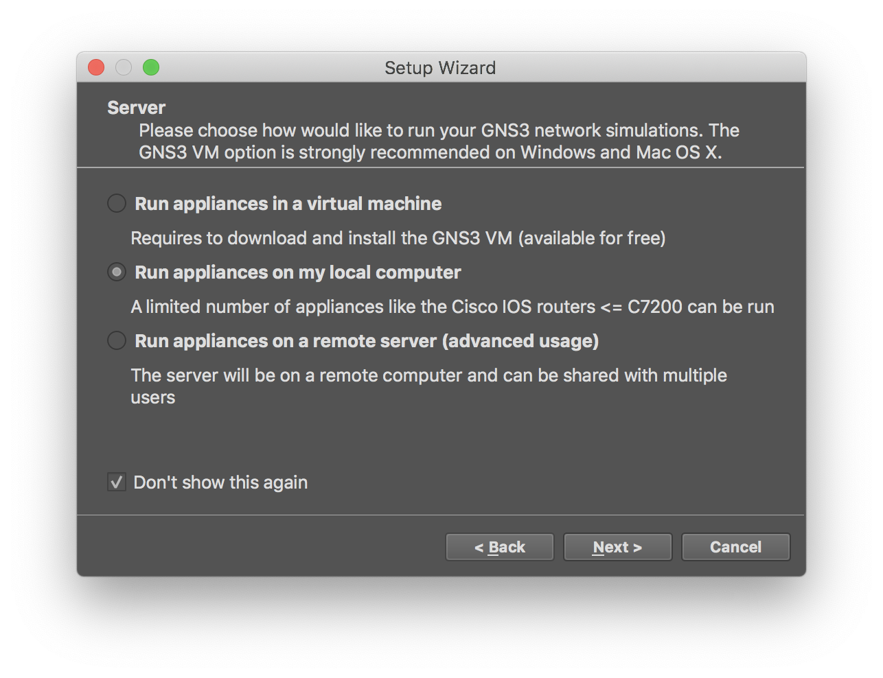
There are multiple ways of running GNS3. For our purposes, we can simply run everything on the host machine (no need for GNS3-VM). So, select options “Run appliances on my local computer” when asked.
4. Install Cisco 3660 and Cisco 7200 templates
Following the walk-through, add templates for Cisco 3660 and Cisco 7200 routers.
For 3660:
-
New template -> Install an appliance from the GN3 server -> Select “Cisco 3660” -> Install -> Install the appliance on your local computer
-
Expand the item and click on .image file (should be marked as Missing)
-
Enable “Allow custom files” checkbox
-
Click on “Import” button and select the downloaded image
-
The image should be now marked as “Ready to Install”, so you can click Next to actually install.
5. Create a project “Lab-1”
In GNS3, create a new project named “Lab-1” containing:
-
Two virtual PCs (VPCS)
-
Cisco 3660 router
-
Cisco 7200 router
Double click on “Cisco 3600” router and in the “Slots” tab add “NM-4E” in the slot 1.
Double click on “Cisco 7200” router and in the “Slots” tab add “PA-8E” in the slot 1.
Links:
-
Connect PC1 (Ethernet0) with R1 (Ethernet1/0)
-
Connect PC2 (Ethernet0) with R2 (Ethernet1/0)
-
Connect R1 (FastEthernet0/0) and R2 (FastEthernet0/0)
6. Run
Click “Run” button to start the emulation. After that, you can double click on individual nodes to start a telnet session to it.
7. Configure IP
Specification:
PC1: 1.0.0.1/24, gateway 1.0.0.254
PC2: 2.0.0.1/24, gateway 2.0.0.254
R1: 1.0.0.254/24; 3.0.0.1/24 R2: 2.0.0.254/24; 3.0.0.2/24
To configure IP on VPCS, e.g., on PC1:
PC1> ip 1.0.0.1 255.255.255.0 1.0.0.254
Checking for duplicate address...
PC1 : 1.0.0.1 255.255.255.0 gateway 1.0.0.254
To configure IP on Cisco boxes, e.g., on R1:
R1#config terminal
Enter configuration commands, one per line.  End with CNTL/Z.
R1(config)#interface Fa
R1(config)#interface FastEthernet 0/0
R1(config-if)#ip address 3.0.0.1 255.255.255.0
R1(config-if)#no shutdown
R1(config-if)#exit
R1(config)#
*Mar  1 00:01:56.043: %LINK-3-UPDOWN: Interface FastEthernet0/0, changed state to up
*Mar  1 00:01:57.043: %LINEPROTO-5-UPDOWN: Line protocol on Interface FastEthernet0/0, changed state to up
R1(config)#interface Ether
R1(config)#interface Ethernet 1/0
R1(config-if)#ip address 1.0.0.254 255.255.255.0
R1(config-if)#no shutdown
R1(config-if)#exit
R1(config)#exit
R1#
*Mar  1 00:02:22.315: %LINK-3-UPDOWN: Interface Ethernet1/0, changed state to up
*Mar  1 00:02:23.315: %LINEPROTO-5-UPDOWN: Line protocol on Interface Ethernet1/0, changed state to up
R1#
*Mar  1 00:02:24.067: %SYS-5-CONFIG_I: Configured from console by console
Note on Cisco, names of interfaces are defined by the type and slot. On a running instance, you can view them by running show interfaces command.
8. Configure static routing on R1 and R2
In order PC1 to communicate with PC2, you need to configure routes. For this lab, we can use a simple static routing.
For example, on R1, you can do the following.
R1#config term
Enter configuration commands, one per line.  End with CNTL/Z.
R1(config)#ip route 2.0.0.0 255.255.255.0 3.0.0.2
R1(config)#exit
R1#
*Mar  1 00:05:33.015: %SYS-5-CONFIG_I: Configured from console by console
Adjust and repeat for R2.
7. Checks
After the above configs, each node in the network should be able to communicate with others. To do the checks, you can go to each node and use ping command.
PC1> ping 1.0.0.254 -c 2
84 bytes from 1.0.0.254 icmp_seq=1 ttl=255 time=8.783 ms
84 bytes from 1.0.0.254 icmp_seq=2 ttl=255 time=7.769 ms
Conclusion / Submission
In Gradescope, submit PDF containing:
-
Page 1: Screenshot GNS3 with the running network
-
Page 2: Screenshot of pings from PC1 to 1.0.0.254, 3.0.0.1, 3.0.0.2, 2.0.0.254, and 2.0.0.1
-
Page 3: Description of any problems, road blocks, what you have learned, what was interesting, not interesting, etc.